
AN41200 Relay Pack Installation Guide
SAFETY INFORMATION Read these instructions carefully and look at the equipment to become familiar with the device before trying to install, operate, service or maintain it. The following special messages may appear throughout this bulletin or on the equipment to warn of potential hazards or to call attention to information that clarifies or simplifies a procedure.
![]() The addition of either symbol to a “Danger” or “Warning” safety label indicates that an electrical hazard exists which will result in personal injury if the instructions are not followed.
The addition of either symbol to a “Danger” or “Warning” safety label indicates that an electrical hazard exists which will result in personal injury if the instructions are not followed.
![]() This is the safety alert symbol. It is used to alert you to potential personal injury hazards. Obey all safety messages that follow this symbol to avoid possible injury or death.
This is the safety alert symbol. It is used to alert you to potential personal injury hazards. Obey all safety messages that follow this symbol to avoid possible injury or death.
|
NOTICE |
|
INSTALLATION • The AN00201 HVAC Controller can be used in conjunction with the AN41200 line voltage switching relay pack. Together they are used as operating controls for high voltage fan coil units. Failure to follow these instructions can result in equipment damage. |
|
NOTICE |
|
LOCATION • Do not install on an exterior wall. Failure to follow these instructions can result in equipment damage. |
![]() All wiring must adhere to local and national electrical code regulations. Carefully read the instructions below before starting the installation. Not following these instructions could result in product damage or create a hazardous situation. A qualified service technician or electrician must carry out the installation. To prevent electrical shock, disconnect the power supply before beginning the installation.
All wiring must adhere to local and national electrical code regulations. Carefully read the instructions below before starting the installation. Not following these instructions could result in product damage or create a hazardous situation. A qualified service technician or electrician must carry out the installation. To prevent electrical shock, disconnect the power supply before beginning the installation.
There are two separate cases for installing the AN41200 Relay Pack.
Case 1: Install Device inside Electrical Cabinet of Fan Coil Unit
1. Use plastic mounting tabs to secure unit to inside of electrical enclosure with screws.
2. Cut one or both plastic mounting tabs if space is needed inside enclosure.
3. Install low or high-voltage metal separator (if required).
4. Do not exceed the maximum rated temperature of unit (50 °C/122 °F).
Case 2: Install Outside of Junction Box or Electrical Cabinet
1. Using supplied lock nut, secure Relay Pack to either electrical junction box or electrical cabinet of fan coil unit.
|
LED COLOR |
LED OPERATION |
|
RED |
When LED is on, power is applied to the AN41200 Relay Pack. |
|
BLUE |
When LED is on, at least one relay is active |
|
GREEN |
When LED is flashing the HVAC Controller is communicating with the AN41200 Relay Pack |
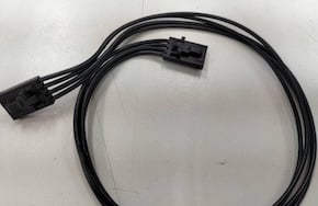
HVAC Controller (AN00201) connection to Relay Pack (AN41200)
The HVAC Controller is connected to the Relay Pack using the Amana PTAC digital interface (4-Pin) wiring harness (AN40900).
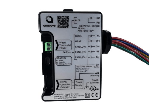
AN41200 - Wiring color coding guide:
***Unused Anacove Wiring should be appropriately terminated***
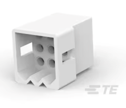
All wires are terminated with TE Connectivity Commercial Pin (350416-1). If the installation requires the use of "Wire Nuts" please cut the commercial pin from the wire end and strip back the wire as required.
The AN41200 is supplied with the TE Connectivity Commercial 9-pin Socket. Do not insert the wires into the commercial socket until the AN412000 Relay Pack is installed.
|
Anacove Wire Color |
Description |
|
Black |
Live voltage, 90 - 300VAC @ 50/60Hz |
| White |
Neutral |
| Green/Yellow |
Ground |
| Orange |
Heating output |
| Yellow |
Cooling output |
| Green |
Low Speed Fan output |
| Blue |
Medium Speed Fan output |
| Brown |
High Speed Fan output |
| Red |
Auxiliary Relay control - independent voltage from the main supply. Rated at 90 - 300VAC @ 50/60Hz |
| Red |
Auxiliary Relay control - independent voltage from the main supply. Rated at 90 - 300VAC @ 50/60Hz |
Specifications:
|
Power Supply
|
90 - 300VAC @ 50/60Hz |
|
Output Ratings
|
Heat Valve: (Orange wire): 5 Amps @ 300 VAC maximum
Cool Valve: (Yellow wire): 5 Amps @ 300 VAC maximum
Fan: (Green, Blue, Brown wire): 5 Amps @ 300 VAC maximum
Auxiliary (Red wires): 5 Amps @ 90 - 300 VAC
|
|
Operating Conditions
|
32 °F to 122 °F, 0% to 95% RH non-condensing
|
|
Approximate Shipping Weight
|
0.75lb
|
|
Agency Approvals all models
|
UL 873 (US) and CSA C22.2 No. 24 (Canada)
CE LVD 2014/35/EU (Europe Union)
CE EMC 2014/30/EU (Europe Union)
FCC Part 15, Subpart B
|
| THIS DEVICE COMPLIES WITH PART 15 OF THE FCC RULES. OPERATION IS SUBJECT TO THE FOLLOWING TWO CONDITIONS: (1) THIS DEVICE MAY NOT CAUSE HARMFUL INTERFERENCE, AND (2) THIS DEVICE MUST ACCEPT ANY INTERFERENCE RECEIVED, INCLUDING INTERFERENCE THAT MAY CAUSE UNDESIRED OPERATION. |
Please check with your local government for instruction on disposal of this product. |